Air drying equipment unit Sukhovei

Air drying equipment

APPLICATION

Air drying unit Sukhovei is designed for:

  • Air drying equipment from moisture
  • air filtration (dust filter)
  • sorbent drying

ADVANTAGES:

  • adsorbent regeneration inside of this unit
  • regeneration of other equipment

SPECIFICATIONS

Parameter Value
1. Dry air capacity, m3 /min , no less than 2.5
2. Dry air dew point, °С, no higher than minus 50
3. Dry air pressure, MPa/bar, no higher than 0.025/0.25
4. Dry air maximum temperature, °С 90±15
5. Adsorbent load per one adsorber, kg, no more than 190
6. Number of adsorbers, pcs. 2
7. Zeolite regeneration temperature, °С, no higher than 430
8. Air heater power, kW, no more than 24
9. Rated power, kW, no more than Air drying (normal operation) 5.5
Adsorbent regeneration in one adsorber 30
Adsorbent regeneration in one adsorbers simultaneously 55
10. Three phase nominal voltage at 50 Hz, V 380
11. Air output temperature for other adsorbent regeneration, °С, not higher than 430
12. Duration of one or two adsorbers regeneration, hours 2-4
13. Dry air filtration fineness, mcm 5
14. Dimensions, mm, no more than: length 1500
width 1200
height 2100
15. Weight, kg, no more than 1050

Air Drying Equipment
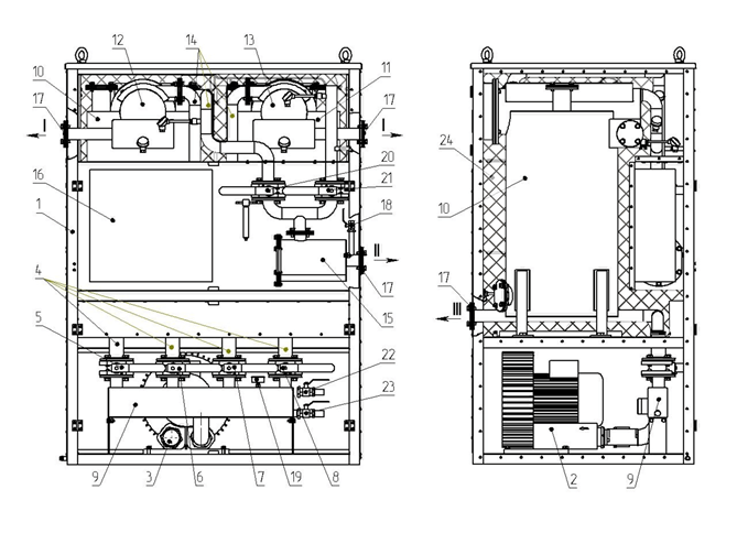
TECHNICAL DESCRIPTION

Dried and purified air can be used for purging of transformer tanks and electrical apparatus during their assembling, servicing and maintenance, it is done for prevention of electric insulation from water intrusion when the active core is open to outside of environment. Unit operation mode – continuous.

COMPONENTS DESCRIPTION

The unit is a metal container, divided into two compartments. The unit operation principle is based on atmospheric air drying in two synthetic zeolite-filled adsorbers, which operate in cycles, dry air is purified from mechanical impurities in dust filter.
I – hot air outlet for adsorbent regeneration in other machines;
II – dry heated air output from the unit;
III – air output after adsorbent regeneration in the adsorber

globecore drying machine sukgovey shceme

General view

1 – container; 2 – air blower; 3 – inlet filter; 4 – compensator; 5,6,7,8 – ball valves; 9 – air distributor; 10 – left hand adsorber; 11- right hand adsorber; 12- lef hand air heater, 13 – right hand air heater; 14 – air ducts; 15 – dust filter; 16 – control cabinet; 17 – plug; 18 – dry air bleed valve; 19 – manometer; 20, 21 – ball valves; 22,23 – ball valves; 24 – insulation.

The air blower 2 is installed in the lower compartment; the blower’s inlet is equipped with inlet filter 3, and the outlet is connected to air distributor 9 with ball valves 5, 6, 7, 8. The air distributor also features manometer 19 and two ball valves 22 and 23 designed for excessive air volume relief, with noise suppressors. The upper compartment is separated into two parts by a screen. One of the parts contains adsorbers 10 and 11 with air heaters 12 and 13. The adsorbers are filled with synthetic zeolites and are insulated with mineral wool. Air ducts 14 are connected to the air heater 12 and 13 to supply air to adsorbent regeneration and to discharge dry air.


Name, reference designation, application and the number of unit main components are given in table and in Flow diagram.

Name and designation Function Amount
Air blower АВ Supplies atmospheric air 1
Inlet filter F1 Prevents debris from entering the suction inlet of the compressor 1
Adsorbers А1, А2 Dry the air by zeolite 2
Air heater AT1 Heats the air for adsorbent (zeolite) regeneration ion adsorber A1 or in external machines, as well as heats dry air at unit output in winter 1
Air heater АТ2 Heats the air for adsorbent (zeolite) regeneration ion adsorber A2 or in external machines, as well as heats dry air at unit output in winter 1
Ball valvesК1, К4, К7, К8 Stop or adjust air flow for drying 4
Ball valves К2, К3 Stop or adjust air flow for zeolite regeneration 2
Ducts Transport the air Set
Moisture sensor MT Measures dry air dew point 1
Manometer МН Measures air pressure at air blower outlet 1
Thermistors РТ1, РТ2 Control air temperature at adsorber outlet when regenerating adsorbent 2
Thermistors РТЗ, РТ4 Control air temperature at adsorber inlet when regenerating adsorbent 2
Thermistor PT5, РТ6 Control dry air temperature at unit outlet 2
Dust filter F2 Removes contaminants from dry air 1
Adsorber output plugsFL1, FL2 The plugs are removed from drain collectors during zeolite regeneration in the adsorber 2
Ball valve К9 Stops and adjust air flow during dew point measurement 1
Noise suppressors NS1, NS2 Decreases noise level when releasing air to the atmosphere 2
Air distributor AD Supplies air 1

The second part of the upper compartment contains control cabinet 16 and dust filter 15 with dry air supply valves 20 and 21, and dry air bleed valve 18.

flow diagramm of oil dryer globecore

Flow diagram

◄ – air flow for sorbent regeneration;
– air flow for drying.
А1 – left hand adsorber; А2 – right hand adsorber; AT1 – left hand air heater; AT2 – right hand air heater; AB – air blower; F1 – inlet filter; МН – manometer; К1-К4, К7,К8 – Dn 50 ball valves; К5, К6 – Dn 25 ball valves; AD – air distributor; FL1, FL2 – adsorber output plugs; РТ1 – РТ6 – thermistors; F2 – dust filter; MT – dew point sensor; К9 – Dn 15 ball valve; NS1, NS2- noise suppressors.

The unit operates in one of the two modes: air drying and adsorbent regeneration (restoration of performance of moist synthetic zeolites by purging with hot air at 390 – 430 °С).

ADSORBER

The left hand adsorber (A1) is a cylindrical tank with lower connector 2 and upper connector 3. The upper connector 3 is also the air heater case. A support web is welded to the lower part of the case 1, which hold holds the adsorbent layer, and thermistor 6. A connector 7 is installed in the lower part of the adsorber.

adsorber-of-globecore-oil-dryer-600x511

1 – case; 2 – lower connector; 3 – upper connector; 5 – adsorbent; 6 – thermistor РТ1; 7 – adsorbent unload outlet; 8 – adsorbent load inlet; 9 – dry air outlet; 10 – air heater inlet for adsorbent regeneration; 11 – air distribution hopper; 12 – hot air outlet for regeneration of adsorbent in other machines; 13 – thermistor РТЗ; 14 – air outlet for regeneration of adsorbent in the adsorber.

The right hand adsorber (A2) is a cylindrical tank with lower connector 2 and upper connector 3. The upper connector 3 is also the air heater case. A support web is welded to the lower part of the case 1, which hold holds the adsorbent layer, and PT2 thermistor 6. A connector 7 is installed in the lower part of the adsorber.

Right hand adsorber (А2)
1 – case; 2 – lower connector; 3 – upper connector; 5 – adsorbent; 6 – thermistor РТ2; 7 – adsorbent unload outlet; 8 – adsorbent load inlet; 9 – dry air outlet; 10 – air heater inlet for adsorbent regeneration; 11 – air distribution hopper; 12 – hot air outlet for regeneration of adsorbent in other machines; 13 – thermistor РТ4; 14 – air outlet for regeneration of adsorbent in the adsorber.

Air heater 12, 13 consists of three heating elements, which are located on heat resistant insulators, placed on steel pins. The heating elements are made of nickel-chrome wire.
The heating elements in each heater are connected in star shape.
Ball valves 5, 6, 7, 8, 18, 20, 21, 22, 23 consist of metal case with internal seal with metal ball inside.

CONTROL CABINET

Air drying equipment

Air drying equipment

WARRANTY

GlobeCore warrants the machinery supplied under this specification against defects in material and workmanship under normal use and service for a period of 12 months from the date of commissioning.

    GlobeCore

    LEAVE A MESSAGE111