Transformer Oil Purification Plant CMM 0.16
- Removes Water from 100 ppm down to 10 ppm in a single pass and down to 5 ppm after 3 passes (ASTM method D-1533)
- Removes Particulate Matter to 5 microns as standard or down to 0.3 micron (optional)
- Improves dielectric strength up to 65 kV
|
№ |
Specifications |
Value |
| 1 | Production capacity, m3/h: | 0.16 |
| 2 | Treated oil parameters: | |
| – water content, ppm, maximum | 5.0 | |
| – purity class (ISO 4406), minimum | 9 (-/15/12) | |
| 3 | Nominal filtration rate, mkm | 0.3…5 |
| 4 | Outlet oil temperature, °С | 60 |
| 5 | Oil Pressure on outlet, Mpa, minimum | 0.2 |
| 6 | Heater power consumption,kW, maximum | 4.8 |
| 7 | Total Power Consumption, kW | 6 |
| 8 | Electrical outlet parameters 50/60 Hz, V | 380/220 |
| 9 | Dimensions, mm, maximum length/width/height, mm | 980/650/1550 |
| 10 | Weight, kg, maximum | 230 |
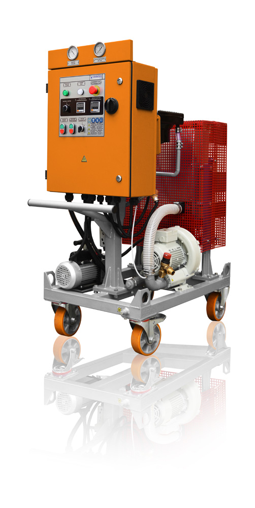
The GlobeCore CMM 0.16 unit the most compact of all GlobeCore Oil Purification Plants and is designed for removal of free and dissolved water and mechanical contaminants from insulating oil, turbine oil, compressor oil and lubricating oils. It is ideally suited for the servicing of transformers and other electrical equipment installed in basements, mines and other places with restricted access. The GlobeCore CMM 0.16 is available in semi-automated, automated (PLC controlled) and explosion proof versions. Optional equipment includes moisture probe, flow meter with totalizer and 0.3 micron fine filter.
GLOBECORE CMM 0.16 COMPONENT DESCRIPTION
 GLOBECORE CMM 0.16 COMPONENTS DESCRIPTION
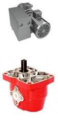
Vacuum System
Rotary Vane Positive Displacement Pump
Pumping Speed 7 m3/h
Ultimate pressure 0.5 mbar
Oil Pump
Gear pump with power consumption of 0.7 kW and capacity of 0.8 m3/h is utilized to draw oil in and out of the vacuum system. Electric motor is protected by an overload sensing device.
Vacuum Chamber and Oil Heater
The Vacuum Chamber and Oil Heater are both mounted in the same Steel Vessel to reduce the unit’s overall weight and dimensions.
The Vacuum Chamber has an oil sprayer provided to maximize exposure of oil to the effect of vacuum.
The Coalescer Filter is installed between the Vacuum Chamber and the Vacuum Pump to ensure that no oil is drawn into the Vacuum Pump.
A 4.8 kW Oil Heater with low watt density heating elements, (1.2 W/cm2) comes complete with thermometer and thermostat. Optionally, the heater can be controlled by an electronic temperature controller or PLC.
 Filters
A Mesh Strainer is provided to remove large particles that could cause damage to the Inlet Pump. A Coarse Filter for particles larger than 5 microns is installed at the entry port to the Vacuum Chamber. Oil then receives its final treatment by passing through the Fine Filter designed to remove 99.9% of particles larger than 2 microns or with an optional 1 micron capability.
Instrumentation and Controls
The Control Panel is placed a dust proof enclosure to IP 54 featuring the following elements:
Manometers – are installed to monitor the state of the Coarse and Fine Filters.
Vacuum Meter is provided to monitor vacuum level in the Vacuum Chamber.
Temperature controller (optional) – receives a data input from a temperature sensor that is connected to a control element of the heater.
Power and Heating Indicators and Switches, Oil Pump Switches and PLC with Mnemonic Diagram (optional).
Emergency Stop Button – is provided for safe shut down of the plant in case of emergency.
 OPTIONAL EQUIPMENT
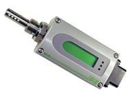
Moisture Probe
The transmitter provides on-line transformer oil measurement of both the moisture content and the temperature. The unit comes complete with a display showing the level of moisture in a “ppm” readout.
 Flowmeter
The “Influx Flotrack” flow meter gives a reading in m3/h and a totalizer shows the total amount of flow passed through the meter in a given period of time.
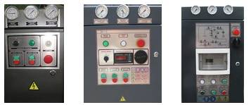
1 2 3
1-Manual, 2-Semi Automated, 3-Fully Automated
GlobeCore Worldwide Sales

GlobeCore CMM 0.16 Flow Diagram
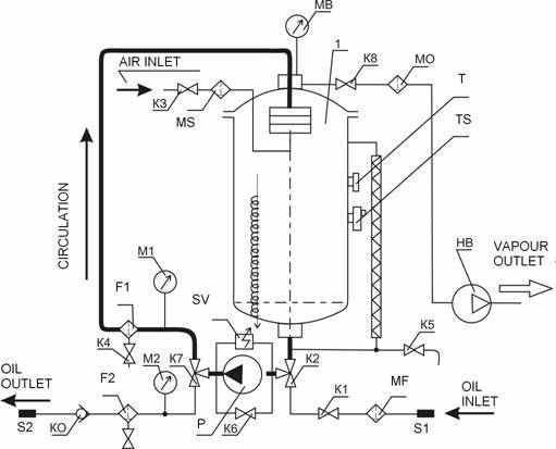
1– vacuum chamber, P– gear pump; VP – vacuum pump; МV– vacuum meter; М1-М2– manometers; F1– coarse filter; F2– fine filter; MF– mesh filter; SV– safety valve; KO– return valve; МО– coalescer filter; Т– bimetallic thermometer; ТS– thermostat; К1– inlvet valve D20; К3-К5– drain valves D15; К6– by-pass valve D 15; К2, К7– three-way ball valves D 15; S1– oil inlet; S2– oil outlet